
Too fast if you ask me!
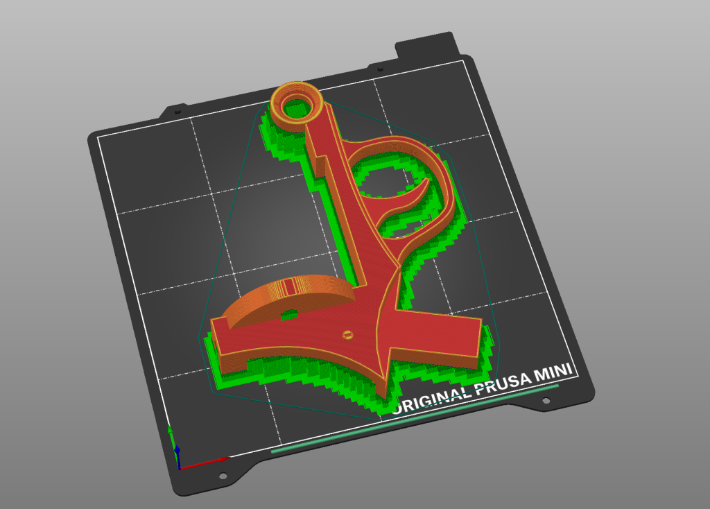
So what’s going on here? Well, I took my Samaritan 3D model and decided to go the next step of 3D printing. It was a little difficult to chop it up into moderately sized chunklates but I managed. Basically I had to, excluding the cylinder itself, split every object in half otherwise there would be just way too much support material for every object. Plus if you keep the orientation similar on each print meaning you line it up with the X and Y axis of the printer you get better hidden print lines which makes the overall printed feature look a lot better. Regardless what happened here?
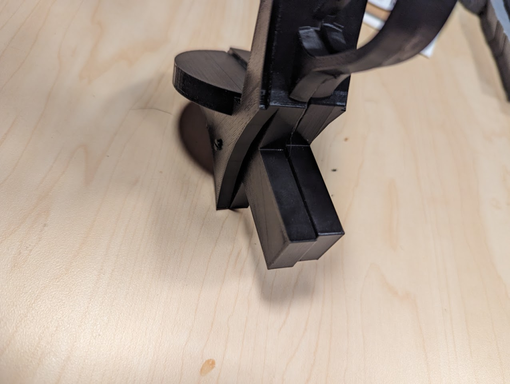
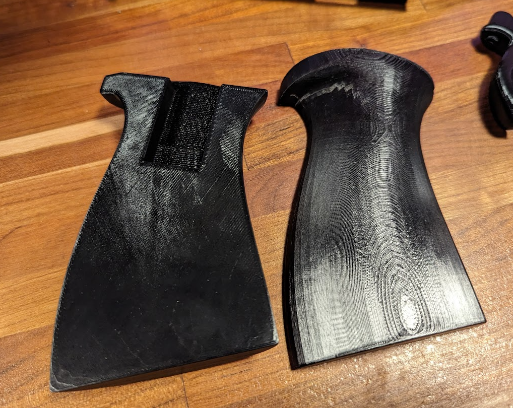
So what are we looking at? Well we’re looking at a pretty large size Gap. The way I designed the main body pieces is that they would be divided in half vertically, print each side, and then put the sides together with some glue. Unfortunately I didn’t put any pegs or any guides that would help me plastic line itself up so unfortunately I’m getting a huge gap as well as it being off-center. Considering that base has to drop into the handle, not lining up is going to cause huge problems.
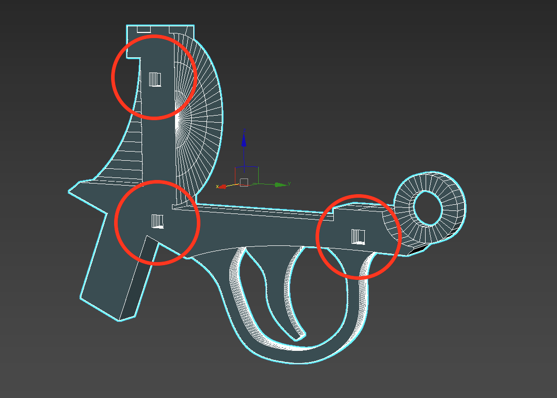
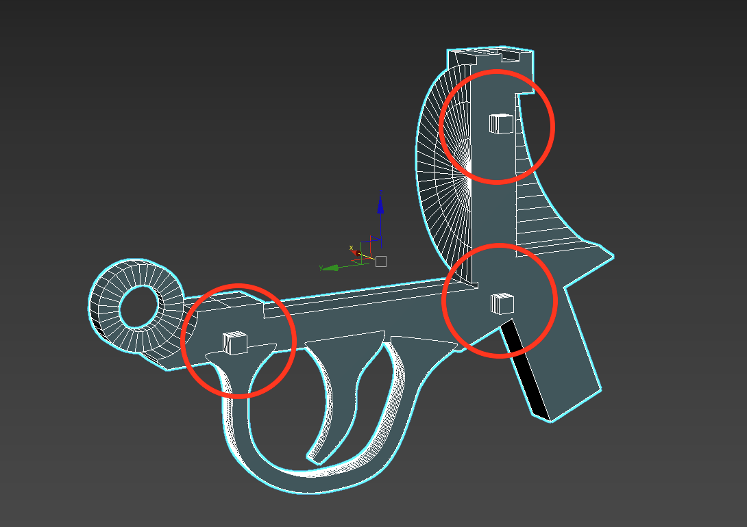
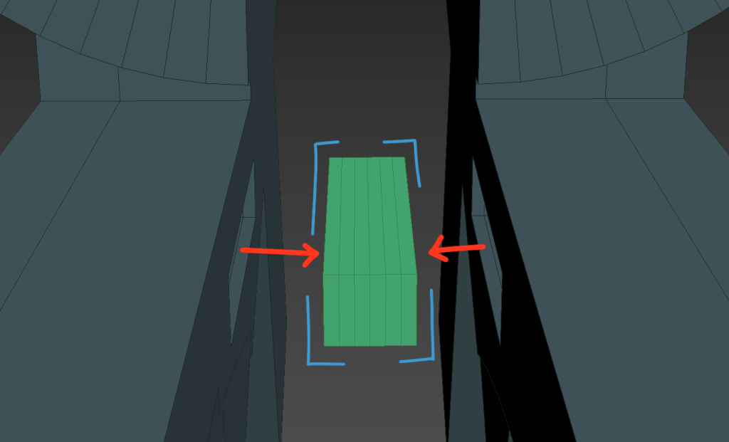
So we found the problem, the problem being that we need to make sure the symmetrical sides line up better. But how do we solve the problem? There might be a fancier or quicker solution in the printing software I use PrusaSlicer where you can add some geometry that helps slot your items together, but I thought it would be a better experience to learn or at least practice how to make my own slot configuration. I didn’t make them snap, I’m not that far yet but I did just make rectangular inserts that each side, one having a protrusions and the other having receptacles, would line up together and do the work of maybe some sort of clamp device to hold them in place. This way they line up perfectly without having to get any extra tools involved (besides glue).
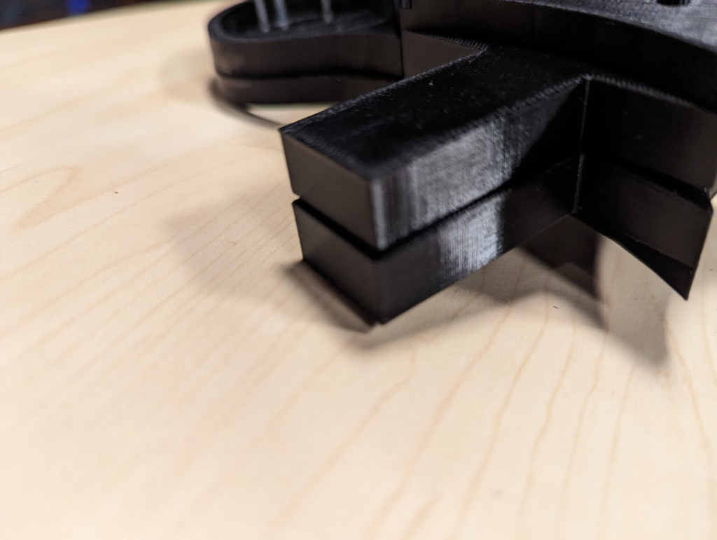
These are actually two separate rectangles with six length segments across that you can see across. So the measurements on the outside rectangle are 6 mm across, by 5 high and five length. It’s difficult to see but rectangle on the inside is only .1 millimeters offset subtracted from the larger rectangles dimension on all sides. Why is that?
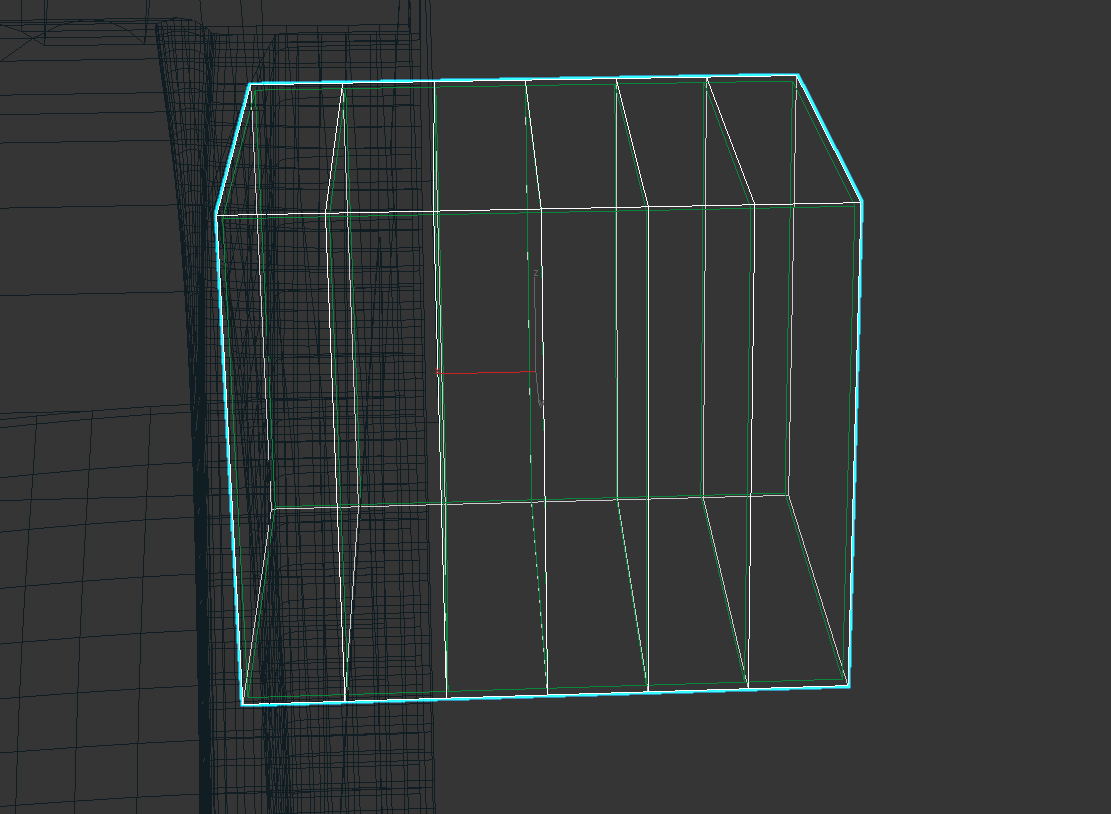
The reason is because every 3D printer, I guess not just the printer itself but every type of filament you use, when it prints not only is it extruded in a kind of donut shape but depending upon a myriad of different variables your 3D print will dry and during that process while it rests it changes shape.
When it rests things that are printed to the exact specifications to inset into each other will be too tight. It’s kind of like when a screw and bolt are put together during a normal temperature, depending upon if it gets hotter or colder it’s much more easy or difficult to pull apart. The tolerance changes just barely. Same thing happens with the plastic coming out of your printer. It is designed to a specification but because of the material itself it changes only small amounts. So my printer’s tolerance is about .05 mm on all sides when it dries or cools. So with these cubes that are inset it’s easier just to take off 0.1 mm on all sides so they easily intersect.
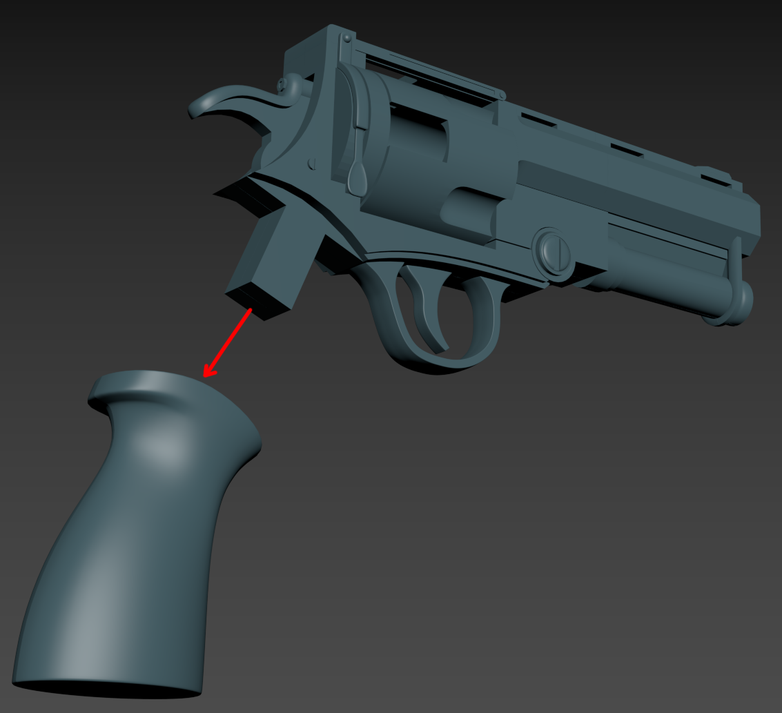
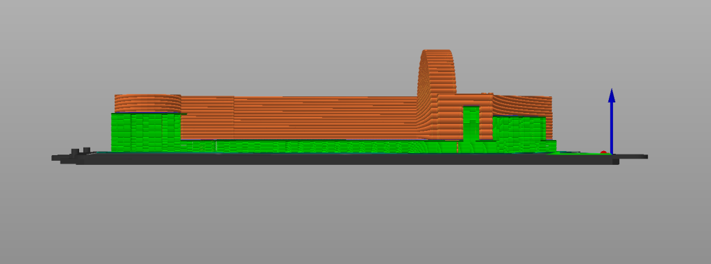
So this Peg idea sounded like a great fix, unfortunately one of the problems is that it causes your 3D print to use not just more filament but it has to be elevated like the pictures below to accommodate the pegs.
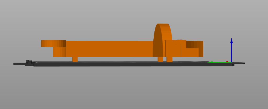
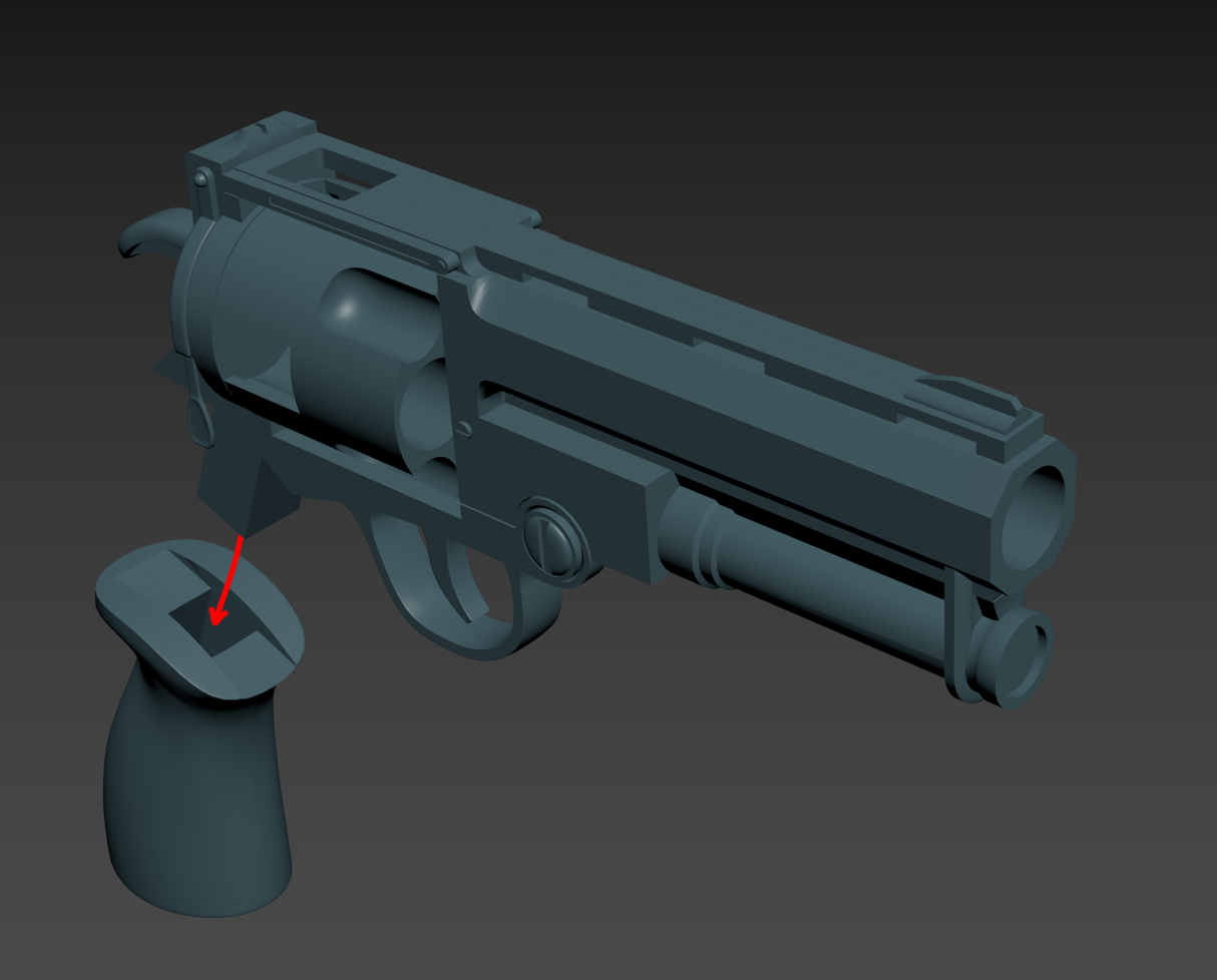
So what’s the solution? Well hopefully something symmetrical so that each side can print flat. What I came up with I think is what’s referred to as a ‘jig’ which in this case is just a item that is used to measure and line up the two halves so that they won’t be offset. By using something like this we’re cutting down on a significant amount of filament but we’re also adding another object to print. On the inside I created a simple rectangle with essentially the same size as the pegs I was going to use at 25 millimeters long, by 5 wide, by five tall. The inset for this rectangle is modeled on both sides and also has a tolerance of 0.1mm built in so it’s larger than the jig itself. This way it will fit perfectly when they get merged together.
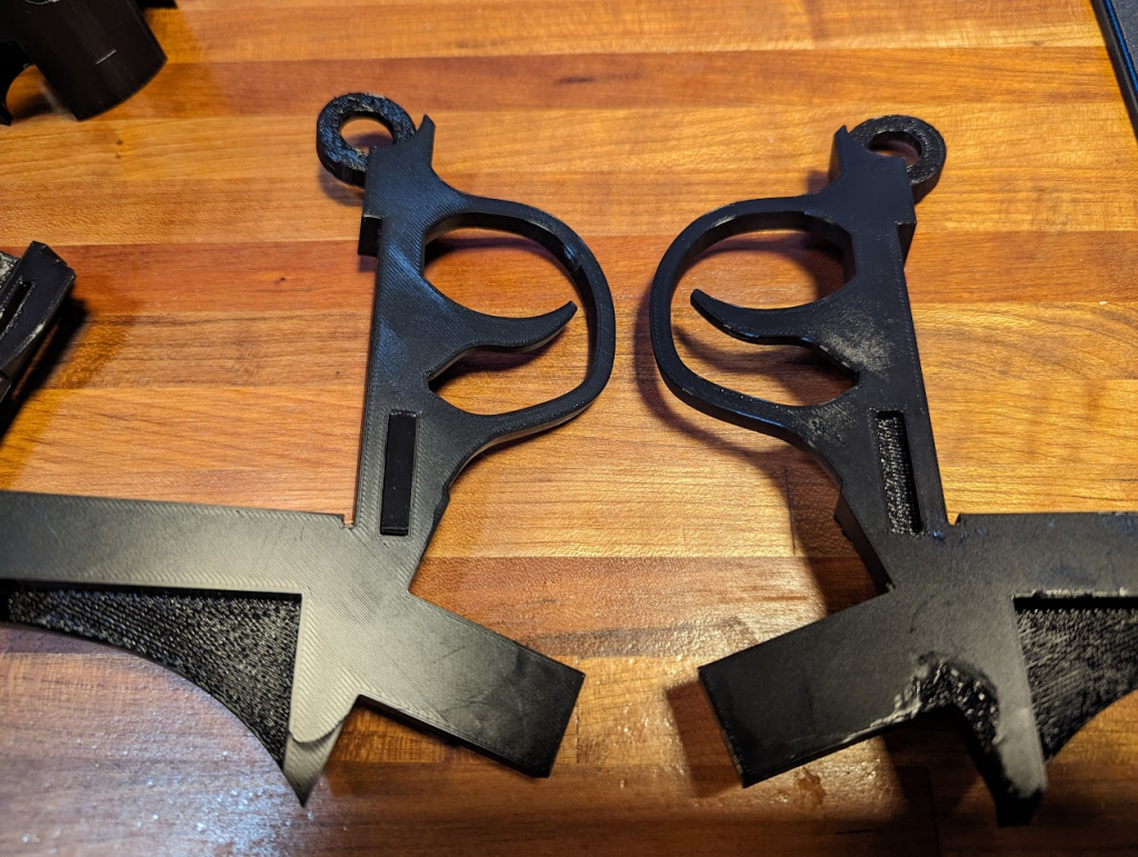
Fantastic! This idea worked quite a bit better than I think the pegs would have even with an extra amount of filament.
Additional note: Unfortunately my printing is not the best. The printer itself is incredible, it’s a great device and I’m sure people better than myself can squeeze a lot of good stuff out of it. One of the problems is I am unable to do any kind of modifications or calibrations to it because of my physical issues. I rely on my fantastic wife and the people that take care of me who don’t specifically like electronics a whole lot to help me work on these projects. So as you can see from the picture above there are some printing fragments where maybe the nozzle touched the inside and it kind of left some strange fragments but overall those are being hidden on the inside here. If you look at the picture below it’s almost perfect. Even though they’re likely not reading this, I appreciate everybody who’s helping me with this project, putting up with the different trials with connecting pieces, using super glue, and of course restarting the prints when they go awry!
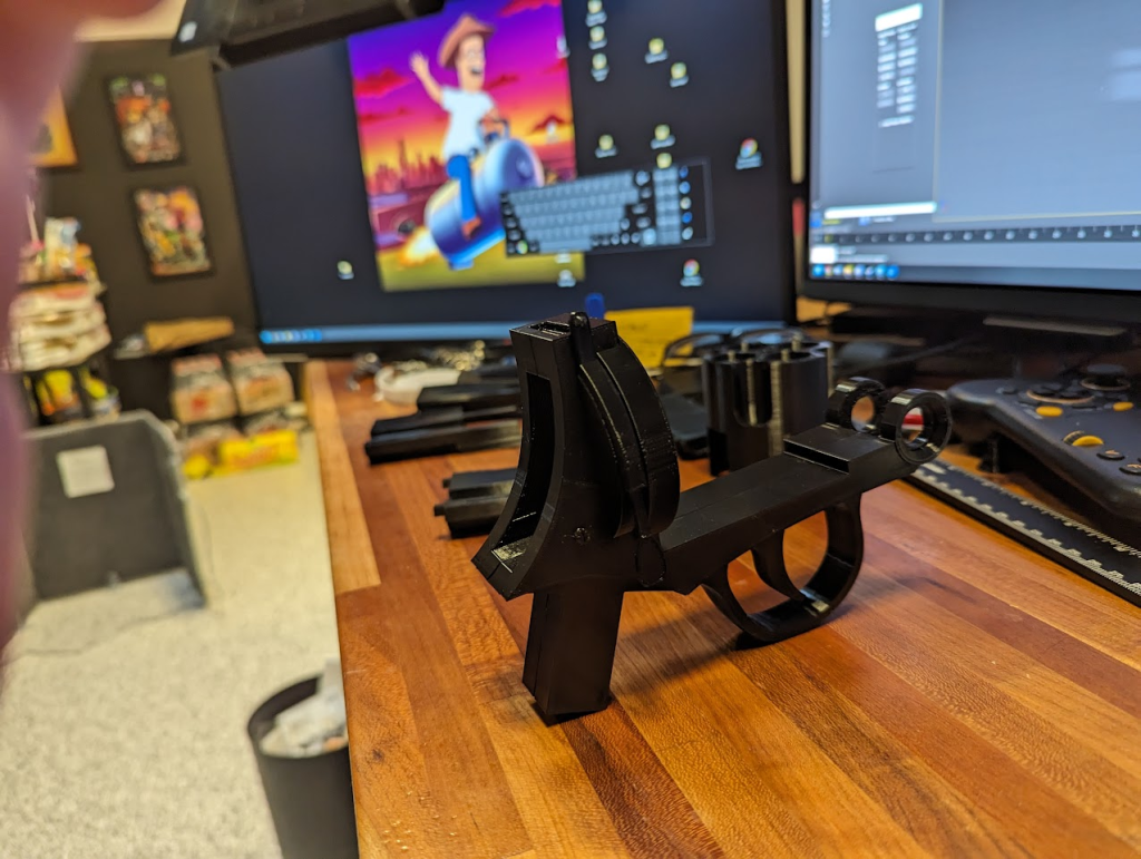
We’ve got the main body part done. Not sure when it’s going to be complete but still working on it!
Thanks for checking it out!
-mh